
MV motor monitoring
Continuous condition monitoring from inside the MCC.
Medium-voltage motors run the largest assets in the plant. Their failures are the most expensive, their outages the longest, their PD tests the most disruptive. SAM4 reads the current at the switchgear and watches the stator and rotor every second of every day.
Most MV motors are checked once a year. Failures don’t wait that long.
MV motors operate at 1–13.8 kV and drive critical process equipment. Stator insulation degradation accounts for 28–40% of failures, far higher than on low voltage motors. The standard diagnostic is an annual offline partial discharge (PD) test during a planned shutdown. Between tests, insulation condition is invisible.
of MV motor failures originate in stator winding insulation, driven by thermal aging, partial discharge, and contamination. (IEEE/EPRI reliability data)
typical replacement lead time for an MV motor. Large synchronous machines can exceed 12 months. Early detection is the only path to planned intervention.
between standard offline PD tests, the industry-accepted interval. Faults that develop between tests progress unmonitored until the next shutdown.
Continuous electrical monitoring from the MCC
The same technology that reads above 95% recall on low-voltage motors now covers medium-voltage. The principle is identical: electrical, mechanical, and process faults all reveal themselves in the motor's electrical signature. SAM4 reads it at the cabinet, nothing on the machine, with MV-rated CTs up to 36 kV.
Electrical faults like winding degradation, imbalance, and supply quality appear directly in current and voltage. Mechanical faults like unbalance, rotor-bar damage, and bearing wear modulate the current through torque and the air-gap field. Process and load changes show up as load-pattern shifts. One measurement at the cabinet carries all three.
Nothing mounted on the motor
All measurement is in the cabinet: split-core CTs clip around the supply conductors, voltage taps at the panel. Nothing is fitted to the motor. On MV, where access is hard and hazardous zones make motor-mounted sensors costly, you monitor the whole fleet, not just the assets you can reach.
Continuous, not once a year
SAM4 runs during operation and catches the fault as it develops. The PD test sees the motor once a year. SAM4 gives the trend in between, while you can still plan.
The layer between your tests
SAM4 trends stator, rotor, supply, and insulation faults from the current. It does not replace offline PD or vibration. It fills the gap between shutdowns.
Representative SAM4 dashboard view. The cabinet read produces fault classifications with evidence levels and recommended actions. On MV motors, the same workflow runs against the switchgear-side electrical signature, with Rogowski coils providing the wide-bandwidth read.
Signal flagged
Expert review
Fault classified
Action recommended
What SAM4 detects on this asset, and where it doesn't fit
One table. Each fault class appears once with its signal path, the strength of field evidence on this asset class, and the recommended use of SAM4. MV motors are mission-critical assets where vibration-based PdM and oil analysis remain the established standard for bearing condition and lubrication. SAM4 monitors the electrical envelope: stator winding, rotor bar, supply quality, insulation trending, and the mechanical signatures (unbalance and misalignment) that couple into the current.
| Fault class | Signal path | Field evidence on this asset | Use SAM4 as |
|---|---|---|---|
| Phase loss and voltage imbalance | Direct electrical | Field-validated baselineCross-fleet baseline | Primary monitoring |
| Stator winding faults | Direct electrical | Fault-mode evidenceInduction-motor cohort | Primary monitoring |
| Supply quality (sags, swells, harmonics) | Direct electrical | Field-validated baselineCross-fleet baseline | Primary monitoring |
| Insulation degradation (trending) | Direct electrical | Fault-mode evidencePrecursor between PD tests | Primary monitoring |
| Rotor bar degradation | Electromechanical | Case-led, cohort buildingMV cohort building | Conditional |
| Eccentricity (static and dynamic) | Electromechanical | Case-led, cohort buildingMV cohort building | Conditional |
| VFD harmonics and switching faults | Direct electrical | Fault-mode evidenceABB ACS600/800 need review | Conditional |
| Mechanical unbalance | Electromechanical | Fault-mode evidenceMV-specific cohort building | Primary monitoring |
| Misalignment with the driven asset | Electromechanical | Fault-mode evidenceMV-specific cohort building | Primary monitoring |
| Bearing degradation | Transmission path | Case-ledVibration leads on MV bearings | Late-stage detection |
| Absolute PD value and source location | Outside envelope | Not a SAM4 claimPicocoulombs, coil location | Use other methods: offline PD |
| Stator core hot spots, thermal faults | Outside envelope | Not a SAM4 claimNot coupled to current | Use other methods: thermography, RTDs |
| Lubrication and grease condition | Outside envelope | Not a SAM4 claimChemical state | Use other methods: oil analysis |
ESA alongside vibration and PD testing: not instead of them
MV motors with high failure consequences already have vibration monitoring and periodic PD testing. ESA adds a continuous electrical monitoring layer that fills the gaps between those measurements. For fleet motors that lack individual monitoring, ESA provides the first layer of coverage at a fraction of the per-motor cost.
ESA from MCC
- Continuous rotor bar condition
- Mechanical unbalance and misalignment
- Load anomaly detection
- Electrical supply monitoring
- Basic insulation screening (trending)
- Energy efficiency tracking
- No motor-mounted sensors
What overlaps
- Bearing trending (rolling element only)
- General health trending
PD testing + vibration
- Quantitative PD measurement (picocoulombs)
- PD source location within specific coils
- Sleeve bearing monitoring (proximity probes)
- High-frequency bearing defect detection
- Shaft position and orbit analysis
- Standards-based severity assessment (ISO 20816, IEEE 1434)
Recommended monitoring by scenario
Critical >2 MW compressor drive
Critical >2 MW compressor drive
Full stack: vibration (proximity probes), online PD, temperature, oil analysis, shaft voltage monitoring. ESA adds load profiling and a second opinion on rotor condition. Does not replace any of the above.
Fleet of 20 pump motors (200–500 kW)
Fleet of 20 pump motors (200–500 kW)
ESA across the full fleet from the MCC. Continuous vibration on the 3–5 most critical. Annual offline PD on all. This is where ESA’s economics are strongest: fleet-wide coverage where per-motor investment is not justified.
VFD-driven mill motor
VFD-driven mill motor
Shaft grounding (mandatory), vibration for fluting detection, online PD if >1 MW. ESA adds load profiling and rotor assessment, but VFD harmonics limit detection quality. Requires VFD-aware signal processing.
MCC installation. No motor access required.
1. Access the MCC or switchgear
SAM4 installs at the motor control centre, the same panel your electricians already access. No hazardous zone entry, no motor terminal modifications. MV arc flash safety requirements apply: qualified personnel, energised work permit, or installation during planned outage.
2. Install Rogowski coils on motor supply cables
CTs clip onto individual motor phase cables. No saturation risk, wide bandwidth for accurate harmonic analysis. Split-core design allows retrofit without disconnecting cables. Works with DOL, soft starters, and MV VFDs.
3. Connect and commission
The SAM4 gateway connects via cellular (4G/LTE), no dependency on your IT/OT network. Monitoring starts immediately. Baseline establishment requires several days of normal operation. Per-motor commissioning sets thresholds for the specific motor and drive configuration.

Other asset types SAM4 monitors
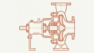
Pumps
Centrifugal pumps in water, chemicals, oil & gas, and process industries.
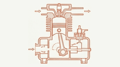
Compressors
Reciprocating, screw, and centrifugal compressors across process industries.
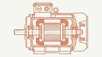
LV motors
Low voltage motors across all industrial applications.
Fans & blowers
Ventilation fans, cooling fans, process blowers, and aerators.
See SAM4 on MV motors
A 30-minute demo shows SAM4 running on MV motors, with real electrical signatures, real fault data, and an honest view of where ESA adds value alongside your existing monitoring stack.
How this page is validated
MV-specific evidence base building. The induction-motor physics is shared with the LV-driven fleet baseline, so pathway claims inherit from that body of evidence. Per-fault recall on MV motors will be published when the MV-specific sample reaches the threshold set in our reporting rules. Until then, this page reports pathways and scope.
How the MV evidence base grows
- Each alert SAM4 raises on an MV motor is followed up against customer-confirmed outcomes
- Cases are scored independently: detected, missed, or false alert
- Pathways resolved on the LV-driven fleet inform initial scoping and severity bands
- Field evidence on this asset moves from a clear signal path to case-by-case proof to a published metric as the evidence base grows
What evidence is available today
- Pathway analysis grounded in three-phase induction motor physics, identical to LV
- Fleet-level review of comparable-cohort performance available on request, see the LV motors page for the published baseline
- MV-specific case detail and review criteria available to qualified technical evaluators under engineering review
- Published research on ESA for MV applications referenced in the validation report